Page 1 of 1
G-AXLR: engine pylon and Super vs. Standard wing
Posted: Sat Aug 15, 2009 1:36 pm
by Hobbes
Hi all,
newbie here. I'm building a model of G-AXLR, using the Airfix VC-10 kit, the TwoSix decal set and a resin RB-211. I'm looking for some more information on the engine mount. I've found the photos on this site, but they don't quite show the entire mount. This one suggests there is a small brace in front of the main mount:

but is there? Is there any other source of photos?
This is what I've built so far:

Also, I saw that G-AXLR had the Super VC-10 wing. Are there any drawings online that show the difference?
Thanks,
Re: G-AXLR: building a model
Posted: Sat Aug 15, 2009 7:55 pm
by Hobbes
Ha! I've done some more digging and found
this site that has a conversion set to create the Super VC-10 wing from the Airfix kit:

However, ISTR reading that the wingtips were also a bit different on the Super. That question remains: different how?
Re: G-AXLR: engine pylon and Super vs. Standard wing
Posted: Sat Aug 15, 2009 8:09 pm
by Jelle Hieminga
Hello Hobbes,
All the images I have of G-AXLR are on this page:
http://www.vc10.net/History/Individual/XR809.html The drawings there might be of some help. You've found the Braz conversion kits already, there's more material on this page but you may not need that since you seem to have everything already:
http://www.vc10.net/Misc/vc10_models.html
I don't think that there is a brace in front of the pylon but I'll see if I have a larger version of that image to check.
As for wingtips, have a look at the VC10 C1 images throughout my site and compare them to others. The C1 is a Super/Standard hybrid but the kit was modeled as a K2 which isn't that far off. The wingtips may have a more pronounced curve than the rest of the wing profile, I've seen that on 1103 versions.
Re: G-AXLR: engine pylon and Super vs. Standard wing
Posted: Sat Aug 15, 2009 10:08 pm
by Hobbes
Hi Jelle,
yes, I'd seen the photos on the History page. They're helpful, thanks. I'll have a look at the wing photos.
Re: G-AXLR: engine pylon and Super vs. Standard wing
Posted: Mon Aug 17, 2009 8:35 pm
by Tonkenna
I have a flight international that has some diags of the fitting... send me a pm with your email address and I will email a scan...
Looks great though!
Tonks

Re: G-AXLR: engine pylon and Super vs. Standard wing
Posted: Thu Aug 20, 2009 2:50 pm
by Jelle Hieminga
Hobbes, this is a full size crop of the photo you posted above. My view is that the pylon is uncovered (the fake pylon at the top is also bare) and therefore it looks as if there is a brace while it may be just the leading edge of the pylon. I hope this helps.
Feel free to post more images of your progress.

Re: G-AXLR: engine pylon and Super vs. Standard wing
Posted: Sat Oct 10, 2009 12:58 pm
by Hobbes
Thanks to Jelle's photo and scans mailed to me by Tonks, I've booked some progress:


I've built a pylon that looks much like the original engine pylons for the Conways, extended a bit so the centerline of the engine is in the right place (it's halfway between the centerlines of the Conways).
It looks like the pylons slant upward at the front, as seen in this photo:

There's still some guesswork in my design, but I think this is as close as I'll get, so it's on to the next phase (wings).
Re: G-AXLR: engine pylon and Super vs. Standard wing
Posted: Sat Aug 27, 2011 2:42 pm
by Hobbes
Hi everyone,
I finally found the time to work on this again, the model is almost ready for its decals:


Re: G-AXLR: engine pylon and Super vs. Standard wing
Posted: Sat Aug 27, 2011 4:46 pm
by Tonkenna
Nice to see you've got back to the model... looking good so far, looking forward to some more pics soon.
Tonks

Re: G-AXLR: engine pylon and Super vs. Standard wing
Posted: Thu Sep 22, 2011 2:30 pm
by Hobbes
It's done!
It's been on my bench since August of 2009.


This pod under the right wing contained a bunch of heating elements. These dissipated the electrical power generated by the RB.211.

Thanks to some photos I got from the RR Heritage Centre, I've been able to create an accurate model of the engine pylon.

There were a few last-minute adjustments: I'd neglected to put any weight in the nose, so I've made a small stand out of perspex to support the back end.
The decals need extra attention: the entire decal sheet is one continuous backing film, so you have to cut around each element (unlike 'normal' decals in volume production kits). TwoSix have done the doors as separate elements to the windows, so you have to stack 2-3 layers of decals in some places. If you haven't done this before: practice with some scraps, otherwise you'll get an ugly mess.
A more comprehensive build thread can be found
here
Re: G-AXLR: engine pylon and Super vs. Standard wing
Posted: Thu Sep 22, 2011 9:41 pm
by Tonkenna
Now that looks very very nice... wish I could do that! LOL Infact I have just sold 2 of my VC10 models as I am so bad it would be such a waste!!
Really good job with that conversion, thanks for posting the pics...
Tonks
Re: G-AXLR: engine pylon and Super vs. Standard wing
Posted: Fri Sep 23, 2011 9:13 am
by Jelle Hieminga
That looks really great!! Congratulations on a fine job! I recently got hold of some G-AXLR images that I need to put on the site, I might include one of your model as well.
One thing that puzzles me though: the nose-gear doors look different from what I'm used to. Normally with the gear down they should be closed. Is there a specific reason that you changed them?
And I have to ask... about those photos from the RR Heritage trust... any chance....??

Re: G-AXLR: engine pylon and Super vs. Standard wing
Posted: Fri Sep 23, 2011 11:00 am
by Hobbes
Hi Jelle,
I hadn't realized that the doors were supposed to be closed.
They're also in the wrong position:I installed the gear units first, then I noticed that I couldn't fit the smaller door behind the front wheels. So I put the smaller door at the front of the wheel well instead. I'll take another look and see if I can make a more realistic fit.
Feel free to reuse any of the photos in this thread. Unfortunately the photos from RRHT I received on condition that I don't publish them.
Re: G-AXLR: engine pylon and Super vs. Standard wing
Posted: Fri Sep 23, 2011 8:52 pm
by Jelle Hieminga
Hello,
I've just updated the
G-AXLR page with two new photos from old press releases, including the texts. I figured the would fit in this topic as well:

FOR RELEASE APRIL 23, 1969
NXP/1629227-4/23/69-HUCKNALL, ENGLAND: This retouched photograph shows how a VC10 aircraft will be used by Rolls-Royce for flight testing the RB.211 three-shaft turbofan here at Lockheed's flight and test establishment. This advanced technology engine will power the Lockheed TriStar jetliner which, after a series of severe tests on the VC10, is expected to have its maiden flight in late 1970.
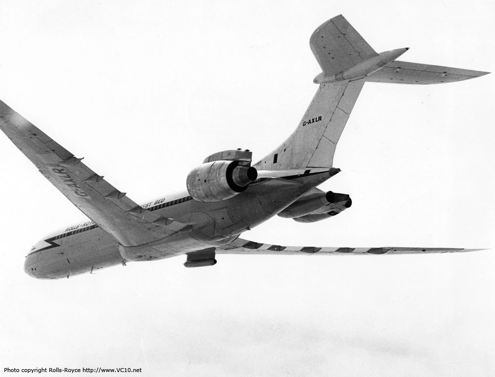
RB.211 FLIGHT TESTING
Handling of the RB.211 three-shaft turbofan in the VC10 flying test bed aircraft is bearing out the predictions made about the engine's power management system. Lockheed TriStar pilots will be able to select the correct thrust for any condition of flight with the maximum efficiency and minimum workload, benefitting both flight safety and engine life.
September, 1970
As an interesting side note: Rolls Royce went bankrupt over the RB211 development costs in February 1971
The Lockheed Tristar did indeed make its maiden flight in November 1970 but it took a while to get the engines up to the required reliability. The end result is in a way still flying on in today's RR powered A380s as those Trent engines are a conceptual offspring of the RB211 design.